Not all PC 12V fans will start spinning at 5V but most modern quiet fans will start and run just fine. I have little to no use for GPIO on VF2, so putting a fan there is completely fine for me.
As stated before, this would complicate the setup for a simple acrylic case like this. Sounds like a good idea for additive manufacturing (3d printed) case if heat on m.2 device is a concern. However I can assure you, a VF2 run in normal temperature environments can physically never overheat NVMe storage.
I found a 25mmx10mm stick on 5v fan made for a raspberry pi, comes with 2 small heatsinks which match the PMIC and PCIE<>USB, cheap on EBay, just had to change to a JST connector.
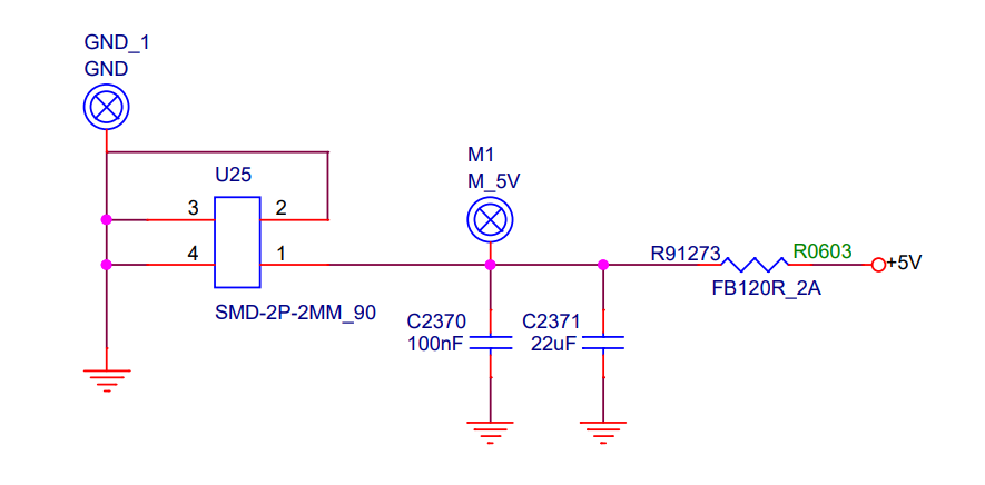
I tried to spot the fan header in the design schematics and i think it is on sheet 21 labeled “U25” there. That would mean, the fan header is in fact not regulated and the 5V GPIO deliver the same flat power. The fan header is a JST PH 2.0 2 pin 2 mm, i think.
Pins 1 and 2 are the socket pins, 3 and 4 are the solder lugs for this SMD component.
The FB120R is the important item here, a 2A ptc/polyfuse, this protects the board from short circuits or anyone trying to use it to drive high-power accessories (use GPIO header for that).
It also means you should not try to power the board through this socket, any serious power spike will drop you well below 5v on the board itself, no matter how powerful your supply.
Unfortunately this SMD socket has a polarised footprint, eg you cant simply de-solder it with a re-flow gun, turn it around and re-paste then solder. It may be possible to buy the same connector with a ‘reversed’ shell, which would have the same effect.
But, it’s also really easy to pop the fan’s plug in a small vice, depress the tiny metal latch and gently withdraw the pin sockets. Then check and if necessary gently press the latches back so they will work when re-used. And finally re-insert the pin sockets the correct way around. I’ve done this numerous times, you just need a steady hand, small tools and good eyesight (I have a nice magnifier to help my old eyes).
IMO, If the manufacturer thought it needed a fan, it would have shipped with a fan.
If the price was right, I’d probably buy sheets of acrylic in that approximate size and drill holes as needed for my collection of boards that are always snagging on things or that I’m having to prop off a desk. Sure, I’d pay more for ones cut more precisely and pre-drilled for VF2. But I didn’t see a link for your US store. Make it easy to us to give you money. (I don’t see this being a spammer as you’re clearly a regular contributing member of this group, but maybe admins might not see that…)
I’ll have the link up in the next couple days - been busy with work and want to get the 60mm plate done. =)
Sure, would be possible. I could even make a PCB for easier UART breakout, maybe even another USB port (since I figure most UART hookups are through USB-UART anyway) and GPIO-controlled 12V fan header. But that’s getting quite involved IMO. The fan always running when plugged in doesn’t bother me. How often would the VF2 be shut down?
Right. The fan would run permanently in any case. And controlling it by GPIO pins means adding extra circuits, as e.g. in this or this post. But having a fan permanently starting and stopping would not help much. Instead, the fan’s speed would need to be regulated, which is in principle possible, but means more GPIO pins and more circuit.
So for a simple construction, and that is, what i am looking for, your solution is well balanced, since the fan is already virtually inaudible. I’ll try this out.
I made the 60mm top plate today. But I can’t find a 60mm fan to test. It should fit though. Made room in the GPIO cutout for accessing the boot switch block.
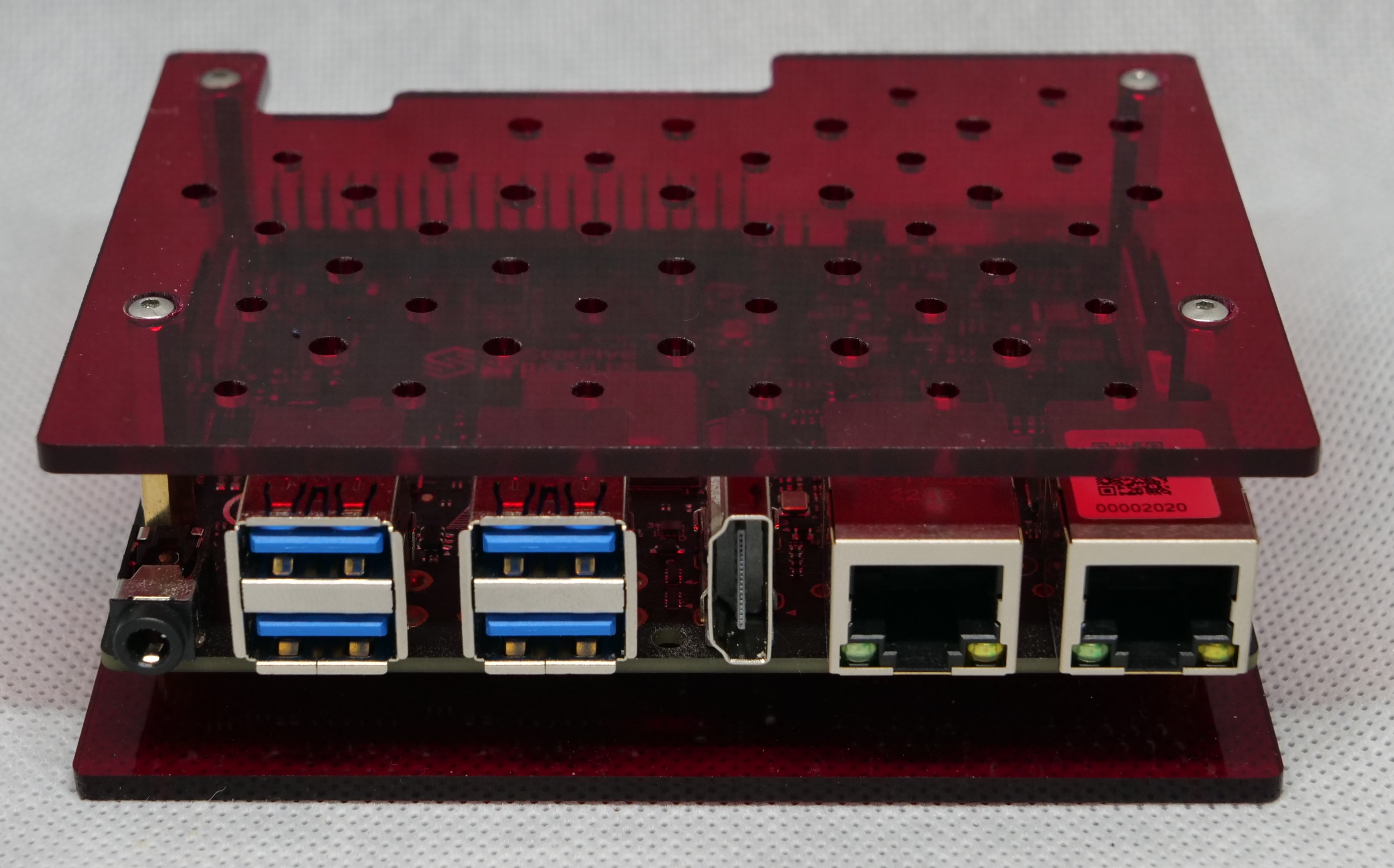
I also created a top plate with 2.5mm and 3mm holes. Can mount standoffs through these with nuts. Should I undersize for self-tapping instead? This is the prototype; the final has a different hole pattern which also has 58x49 M2.5 hole spacing to allow for mounting RPi hats.
The boards and all these accessories are quite delicate. Anything we can do to help minimize single point of failure by reducing the number of times we touch stuff within the case is an improvement right?
I wish the VF2 case would come with usb-uart thingy one of the ports exposed would be a UART dedicated usb port. That way one doesn’t have to worry about the flimsy pins being pulled off the GPIO interface and all you need is a very long usb male to usb male to go to your computer.
I already bought the usb-uart thingy so in another option would be to buy a case that was designed for holding a usb-uart within the case and somehow connecting it to an exposed port on the case making the interfacing with it a more solid connection and the user able to hold the case rather than a small usb connector.
That’s my whole brain fart. Thank you for listening.
It would be possible for me to make an adapter - I wrote about it above. I personally don’t have much use for UART on VF2 so I am fine pulling out an external adapter for updates, but I know some others use UART exclusively. If you and others need USB-UART then perhaps I can look into making something.
It’s a little bit hacky, but the quickest way I can think of with my design would be adding a small hole/slot or two on the top plate. Can pass a ziptie through, and then using a ziptie to secure a USB-UART module. Would that work? Otherwise I’d need to make a custom two-size module (since my case can be two different heights) that secures with the nearby stud.
Hmm, this sounds to be mainly a software thing to be configured in u-boot, but from the current upstream status it is not available, yet, and i think a regular usb-uart adapter is better suited for the purpose. Mine is permanently mounted and probably will be until the u-boot updates settle to something stable, perhaps beyond.
NO, If you mean directly connected. The GPIO pins do not supply nearly enough current to start the fan, it would be very dangerous to try.
ALSO: If you ‘try’ this and then spin the fan by hand, or start blowing on it, etc, it will apply a surprisingly high voltage to the GPIO and Woof! there goes the CPU.
Use 5v from either the GPIO or the Fan plug and a logic-level mosfet from one of the GPIO lines, preferably a PWM one, to control the fan.
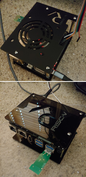
Got my plates from @true today. The top plate is the 60mm matte black with RV logo, and the bottom is the transparent dark smoke - @true threw a RV logo on that as well (thanks!). I haven’t installed a 60 mm fan yet, but my VisionFive2 is turned on with serial console and the wifi adapter both in use in these pictures. I also have an nvme drive installed.
Just realized I never uploaded the SVG and LB files for my acrylic case. I’ve attached them here now. If you make one based on this design, please show us
If you’d like this case and don’t want to make it yourself or source the standoffs and screws, I do sell this case as a kit. I posted the link to buy earlier in the thread, in this post: Case for visionfive2 to buy - #52 by true
Photos of the assembled case are available in the linked post and earlier in the thread.
Oops, there’s an extra hole in the file I uploaded on the 60mm plate (isn’t in my working files, so people who ordered don’t have this problem). It’s on the right side. If making these yourself, remove that extra hole.