Hi !
I am experimenting with a PWM Fan which works fine usind the PWM examples in VisionFive.gpio-1.2.7. However, i can not use the PWM Pins 32&33 (GPIO 46&59).
When i try for example with Pin 32 i get:
user@starfive:~/VisionFive.gpio-1.2.7/VisionFive/sample-code$ sudo ~/pyvenv/bin/python3 RPi_demo_#PWM#_run_on_VisionFive.py
Traceback (most recent call last):
  File "/home/user/VisionFive.gpio-1.2.7/VisionFive/sample-code/RPi_demo_#PWM#_run_on_VisionFive.py", line 11, in <module>
    GPIO.setup(ledpin,GPIO.OUT)
ValueError: The gpio set is invalid on a VisionFive board
Using any of the Pins without special function (in my case Pin 12 (GPIO38) works fine, but the PWM signal seems to be generated on CPU. Using 10kHz as frequency consumes 50% CPU.
So, my question is, how can i use the special PWM signals from GPIO 46&59 ?
I’m not 100% sure how to do that in Python, but I know that you can definitely access those PWM pins as outlined in the GPIO header user guide (page 25 or so):
cd /sys/class/pwm/pwmchip0
echo 0 > export
cd pwm0
echo 1 > enable
echo 50000 > duty_cycle
echo 100000 > period
Where pwm0 (GPIO46) is pin 32 and pwm1 (GPIO59) pin 33.
(When changing the frequency, the duty cycle should be adjusted first, otherwise it’s not going to accept the new frequency if it causes the duty cycle to go above 100%.
Also for reference: The period is entered in ns, so the desired frequency can be calculated via 1/(x*10E-09s). A period of e.g. 100000(ns) results in a 10kHz PWM frequency, and a duty cycle of 50000(ns) = 0.5 * period = 50%)
Hmm, that’s weird. To be fair, I have tried recalling the order from memory, so it can be inaccurate, but I can still remember getting “Invalid argument” errors whenever I set the frequency first (especially when it caused the duty cycle to go over 100%). Perhaps the first time around, the frequency has to be set before setting the duty cycle and enabling it, but for subsequent changes, it should be the correct order.
So for initial configuration:
cd /sys/class/pwm/pwmchip0
echo 0 > export
cd pwm0
echo 100000 > period
echo 50000 > duty_cycle
echo 1 > enable
(Also for further reference, the maximum achievable frequency appears to be about 24.7MHz, with weird duty cycle/selected frequency issues past 10MHz or so. The resulting waveform is also kinda limited by the rise/fall time of the pulses, so the usable bandwith is lower. I’ll probably prepare a short thread about PWM performance on the VF2)
Hey, thanks for the information ! I switched my fancontrol daemon from python to bash and now it works really well !
Here is my script, in case its useful:
#! /bin/bash
#set -vx

# Setup:
# connect a 5v PWM Fan to 5v, Ground and the (yellow) PWM cable to PIN 32 (GPIO 46)

# Configure temperature and fan speed
TEMP_MIN=40
TEMP_MAX=70
FAN_LOW=20000     # this is in nanoseconds
FAN_HIGH=100000   # as period is 100000ns, this is 20 and 100% duty
FAN_OFF=0
FAN_MAX=100000
VERBOSE=0     # 1 for syslog messages on temp/fan changes

get_temp () {
  # Get CPU's temperature
      if [ -e /sys/devices/platform/soc/120e0000.tmon/hwmon/hwmon0/temp1_input ]; then
        res=`cat /sys/devices/platform/soc/120e0000.tmon/hwmon/hwmon0/temp1_input`
      else
        res=`cat /sys/devices/virtual/thermal/thermal_zone0/temp`
      fi
      temp=`echo "$res/1000" | bc`
      echo "$temp"
}

# initialize with 50%
cd /sys/class/pwm/pwmchip0
echo 0 > export 2>/dev/null
cd pwm0
echo 100000 > period    # 100000ns = 10kHz for Noctua Fan
echo 50000 > duty_cycle # initially 50% duty
echo 1 > enable

# fancontrol
while true ;
do
  temp_result=$(get_temp)
  if [ $VERBOSE -eq 1 ];then echo Temp is: $temp_result;fi
  # turn fan off if below TEMP_MIN
  if [ $temp_result -lt $TEMP_MIN ] ; then
     echo $FAN_OFF > duty_cycle
     if [ $VERBOSE -eq 1 ];then echo "Temp below $TEMP_MIN => Fan off";fi
  elif [ $temp_result -gt $TEMP_MAX ] ; then
     echo $FAN_MAX > duty_cycle
     if [ $VERBOSE -eq 1 ];then echo "Temp above $TEMP_MAX => Fan full speed";fi
  else
     step=`echo "($FAN_HIGH-$FAN_LOW)/($TEMP_MAX-$TEMP_MIN)" | bc`
     delta=`echo "$temp_result - $TEMP_MIN" | bc`
     speed=`echo "$FAN_LOW+($delta*$step)" | bc`
     echo $speed > duty_cycle
     if [ $VERBOSE -eq 1 ];then echo "Set speed to $speed";fi
  fi
  sleep 5
done
and wrapped into a systemd service:
/etc/systemd/system/fancontrol.service
[Unit]
Description=pwm fan control
After=network-online.target
Wants=network.target

[Service]
Restart=on-failure
RestartSec=10s
ExecStart=/home/user/scripts/fancontrol.sh

[Install]
WantedBy=multi-user.target
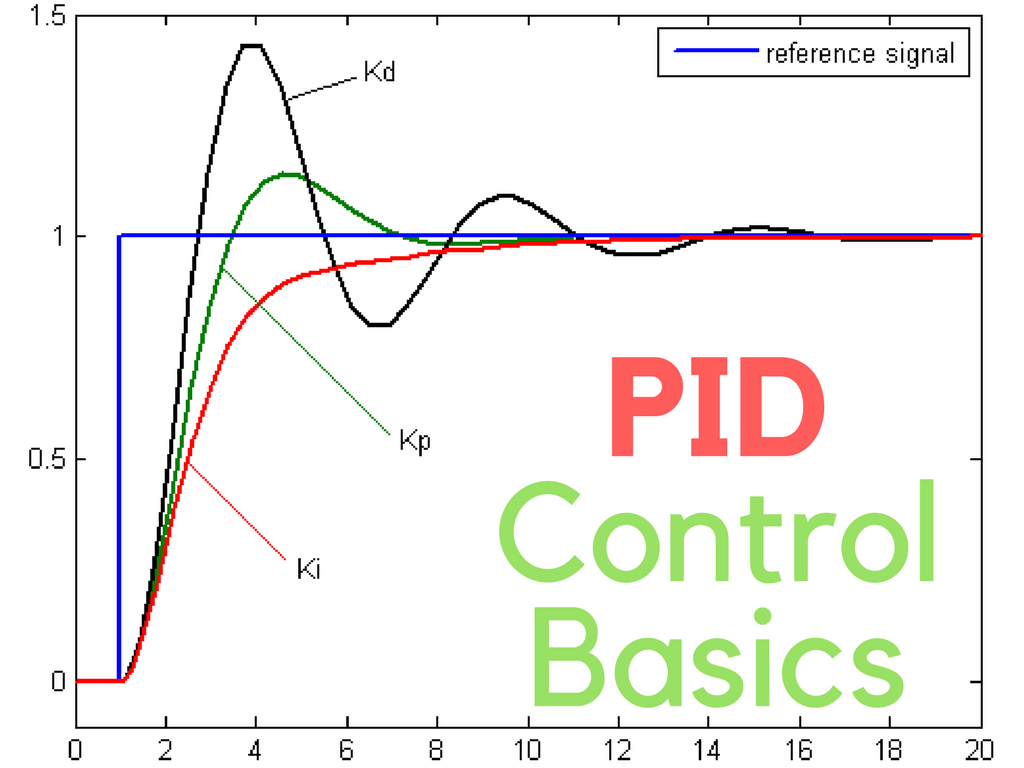
Proportional means that as the temperature gets hotter than the set point the fan gets faster, and as the temperature goes below the set point the fan gets slower.
Integral takes care of any slow changes from the set point over long periods of time, and compensates for that.
Derivative takes care of any rapid changes away from the set point, and compensates for that.
The three combined together generally means better control and lower rates of wear and tear on anything with moving parts. PID controllers have been used for over 300 years!
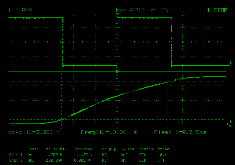
I’ve done a few PWM performance measurements for anybody that’s interested in that sort of stuff.
Frequencies were selected decadically, where necessary delayed sweeps for rise time measurements were added. No further noise rejection or LF/HF filtering has been used.
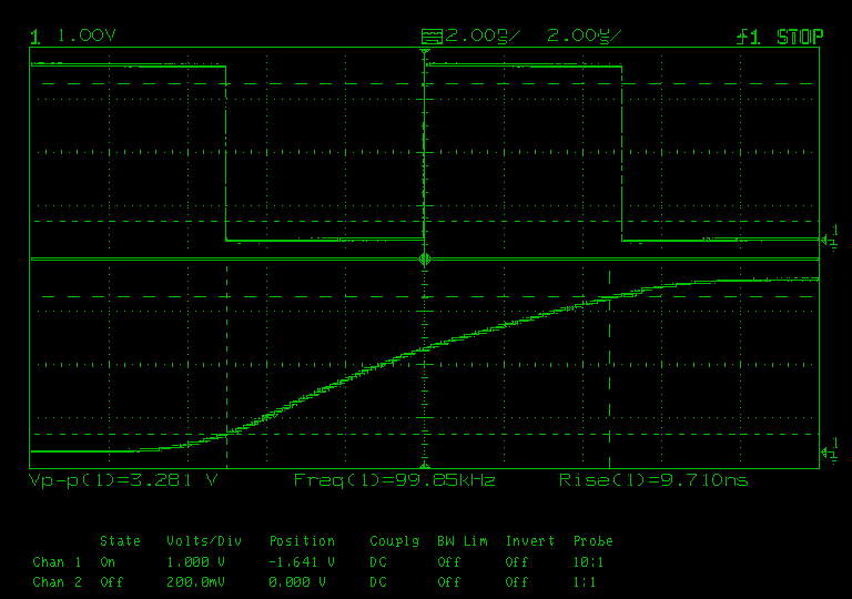
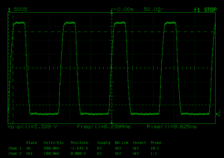
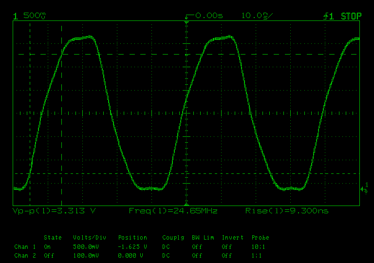
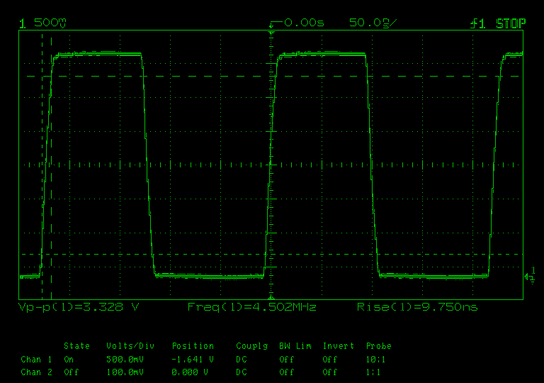
The rise time seems to be consistent at about 9.7ns, which is the main limiting factor for the maximum achievable square wave frequency. I’d say anything from 1Hz - 5MHz is usable, above that the square wave quality starts degrading quickly.
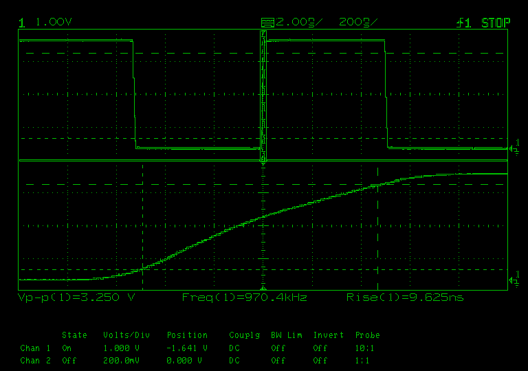
The maximum achievable frequency is ~24.7MHz, however in order to achieve that, a very high frequency needs to be selected on the VF2. Which leads to the next quirk of selected vs. output frequencies, e.g. when selecting 10MHz, the output is about 8.24MHz. This effect starts around 1MHz and persists up to the maximum frequency.
Anyway, for most usecases, the PWM bandwith is perfectly fine.
I don’t have a RPi at hand, but from what I could gather, this seems to be mostly comparable in terms of performance.
These measurements probably aren’t super useful (and I’m sure there is some datasheet for the PWM IC with more accurate measurements), but I hope that you guys still find it interesting.