According to StarFive, developers have successfully used photosensitive sensors on VisionFive 2, and the specific instructions are as follows:
1. Preparation
-
Development board: VisionFive/VisionFive 2
-
Light sensor: Photosensitive sensor with DO output
-
DuPont Line: Many
2. Principle of photosensitive sensors
The specific photosensitive sensor modules used in this demo are as follows:
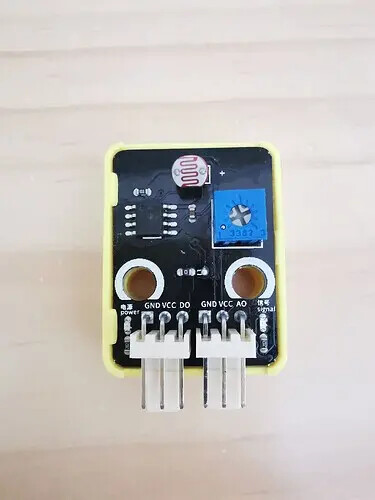
On this photosensitive sensor, a digital output interface (DO) and an analog output interface (AO) are provided.
Because the VisionFive 2 SBC itself does not have an ADC module, this demonstration mainly explains the use of DO output. In the future, we will cooperate with the external ADC module to obtain the intensity value of light through AO output.
At the top of the photosensitive sensor, there is a photoresistor. Due to the photoelectric effect, the stronger the light is, the lower the resistance value will be. As the light intensity increases, the resistance value will rapidly decrease. When the resistance value drops to a certain threshold, DO will output a high-level signal. Otherwise, it will output a low-level signal.
The specific threshold is controlled by the sensitivity adjustment potentiometer on the right side of the module. By adjusting appropriately, a certain intensity of irradiation triggers high-level output for DO.
3. Use of photosensitive sensors
Through the principle of the photosensitive sensor mentioned above, we can know that when the light intensity reaches the threshold, DO outputs a high level, otherwise it outputs a low level. Therefore, we can receive the signal through a digital pin, such as GPIO51.
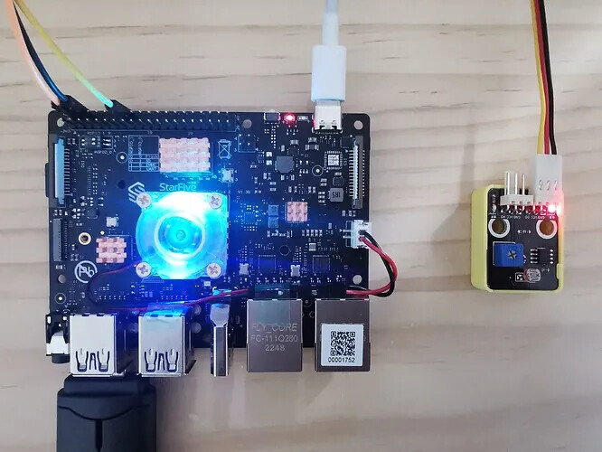
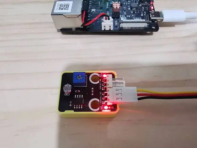
Firstly, refer to the following figure and connect the photosensitive sensor module to the VisionFive 2 (VisionFive):
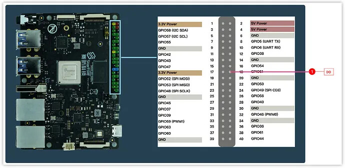
Connection:
Note:
The power supply voltage should be determined based on the actual sensor used. The photosensitive sensor module used in this demo uses a 5V power supply voltage.
Then, write the following program:
# -*- coding: utf-8 -*-
# file: ~/projects/light/light_do.py

# pip3 install gpio
import os
import time
from time import sleep

#import gpio library
import gpio as GPIO
import time

#def gpio pin
GPIO_DO = 51

#setup GPIO work method (IN / OUT)
GPIO.setup(GPIO_DO, GPIO.IN)

while True:
    if GPIO.input(GPIO_DO) == 1:
        print("Threshold Triggered")
    else:
        print("Threshold not reached")

    sleep(1)
The logic of the above program is relatively simple. Through GPIO51, the DO output of the photosensitive sensor module is detected, and different results are output based on the high and low levels.
After writing, run light_do. py, and then try different lighting conditions.
# install GPIO module
sudo pip3 install gpio

# If you encounter an error, you can run *sudo python3 light_do. py*:
python3 light_do.py
The actual results are as follows:
-
When the light is weak, the signal output light on the sensor (pin above the module ) does not light up:
-
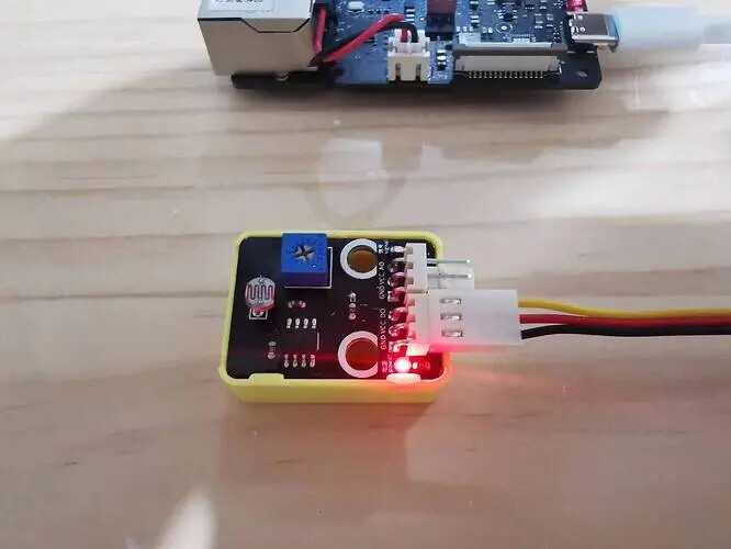
When the light intensity reaches a certain threshold, the signal output light on the sensor (pin below the module) lights up:


4. Summary
In this demo, we learned the basic use of photosensitive sensors.
Photosensitive sensors are used in many situations, such as intelligent light control, anti-theft alarm, etc. Nowadays, many street lights, based on the intensity of the light, can be controlled to light up when the light is weak to a certain extent after sunset, which can effectively optimize the use of electricity.
Author: @HonestQiao