no Boot screen.
flashed SD-Card, mounted Samsung 980Pro 1TB NVMe ssd
adjusted jumpers — can boot from SD but no luck with NVMe image (202306)
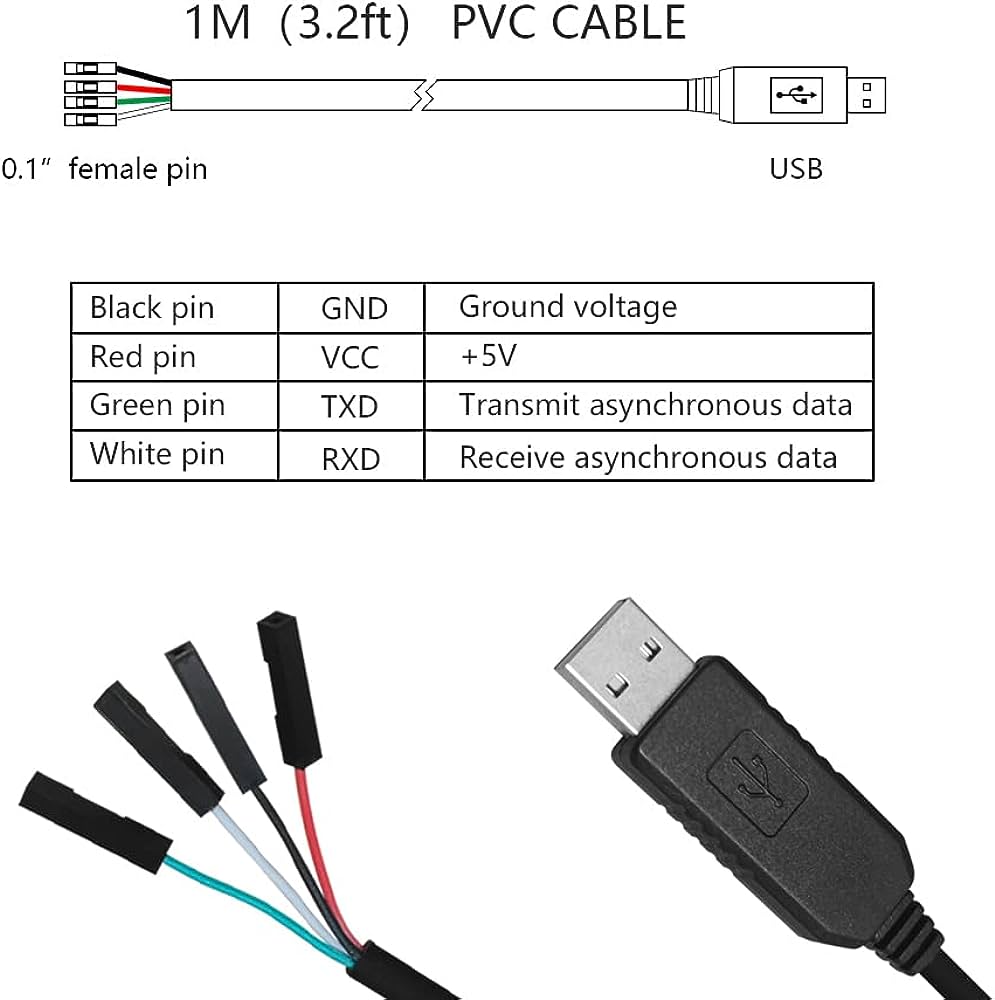
i assume i need to use the USB2TTL connector (part of the bundle) to displaying the boot messages. unfortunately there is nothing to be found in the docs on how to connecting. (the USB2TTL connector has 4 pins (green, black, red and white)
To do this, please connect a second system to the UART of your VF2 using a 3.3V USB-to-serial converter or directly serial-to-serial as described here:
3.4.3. Using a USB to Serial Converter
Please connect only RXD, TXD and GND (as shown in Figure 3-10 Connecting Jumper Wire), never also 5V or 3.3V.
With serial (if it is 3.3 volt) it is safest to use only 3 wires ground(UART)==ground(VisionFive 2), TX(serial)=>RX(VF2) and RX(UART)<=TX(VF2).
It is best to never connect the voltage wire (+3.3 volt and especially not +5 volt), since the board is powered up already, and there is no way that the wire used could carry enough current to fully power up the board. And permanent damage will occur if the GPIO pins (except for the +5V) are accidentally connected to 5 volts.
in principle you are right, but i do not see any u-Boot or SPI info, which i assume ican be seen when using the USB 2 TTK connection. before flashing, I’d prefer to see, whart is going om
Contact the seller for the exact pin out of the “USB2TTL connector (part of the bundle)”
Let’s say that the pin out is:
pin 1 3.3 Volt
pin 2 TXD
pin 3 RXD
pin 4 GND
pin 5 +5 Volt
It will probably be safe to use as long as you only connect 3 wires. That you never connect the first and last pin, because it could never provide enough current to power up the VF2.
But an even safer option, if you only want to see the output, would be to use only 2 wires (there is never any voltage generated by the USB2TTL connector entering the VF2 board, so even if the TX pin on the USB2TTL was 5 volt TTL it can not cause any damage, if it is not connected):