According to StarFive, developers have successfully used temprature sensor on VisionFive/VisionFive 2, and the specific instructions are as follows:
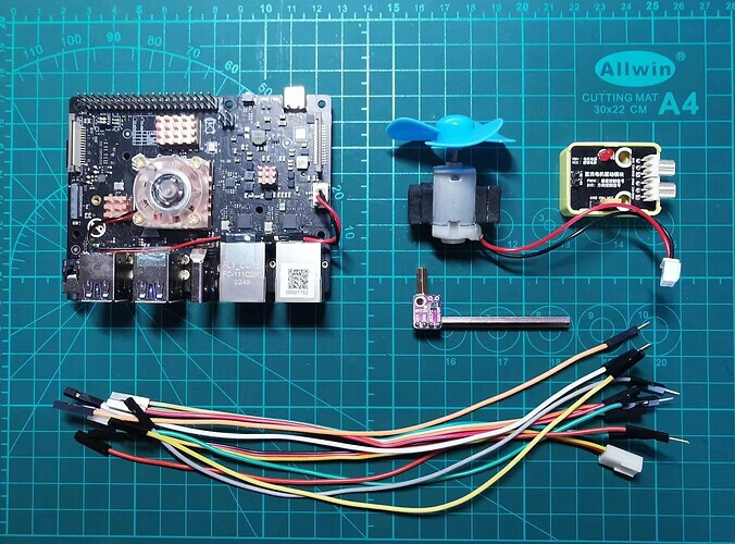
1. Preparation
- Development board: VisionFive/VisionFive 2 SBC
- Temprature sensor: SHT30 temprature sensor
- Motor drive module: 5V DC motor drive module
- Motor: 5V DC motor with fan
- Digital Power: DC CNC power supply, which is used to power the motor
- DuPont Line: Many


2. The principial of fan control
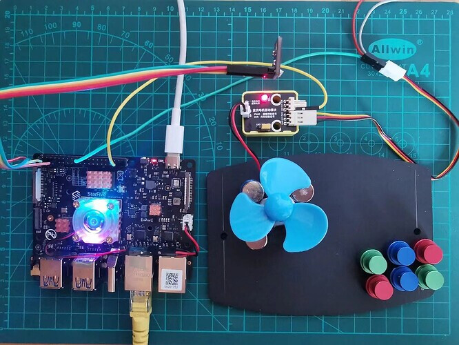
The specific motor driver module and motor used in this demo are as follows:
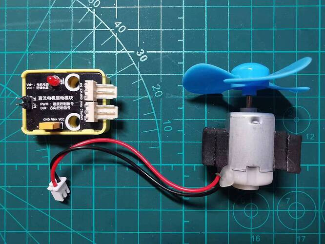
On this motor drive module, there are PWM and DIR in the input interface, where DIR is used to control the direction of motor rotation and PWM is used to control the speed of motor rotation.
The core of PWM is the duty cycle, which is the duration of high level maintenance within a cycle, thereby controlling the average voltage during the cycle:
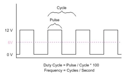
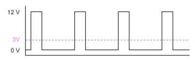
In this demo, we first read the current temperature value from the temperature sensor, then perform a certain conversion, and set the PWM output duty cycle to achieve control of the average voltage of the motor, ultimately manifested as fan speed control.
Due to the relatively high operating current of the motor, it is generally necessary to provide separate power supply to the motor, and the motor drive module is usually used for power supply and control.
3. Connection
At first, refer to the following figure and connect the temprature sensor and motor driver to VisionFive:
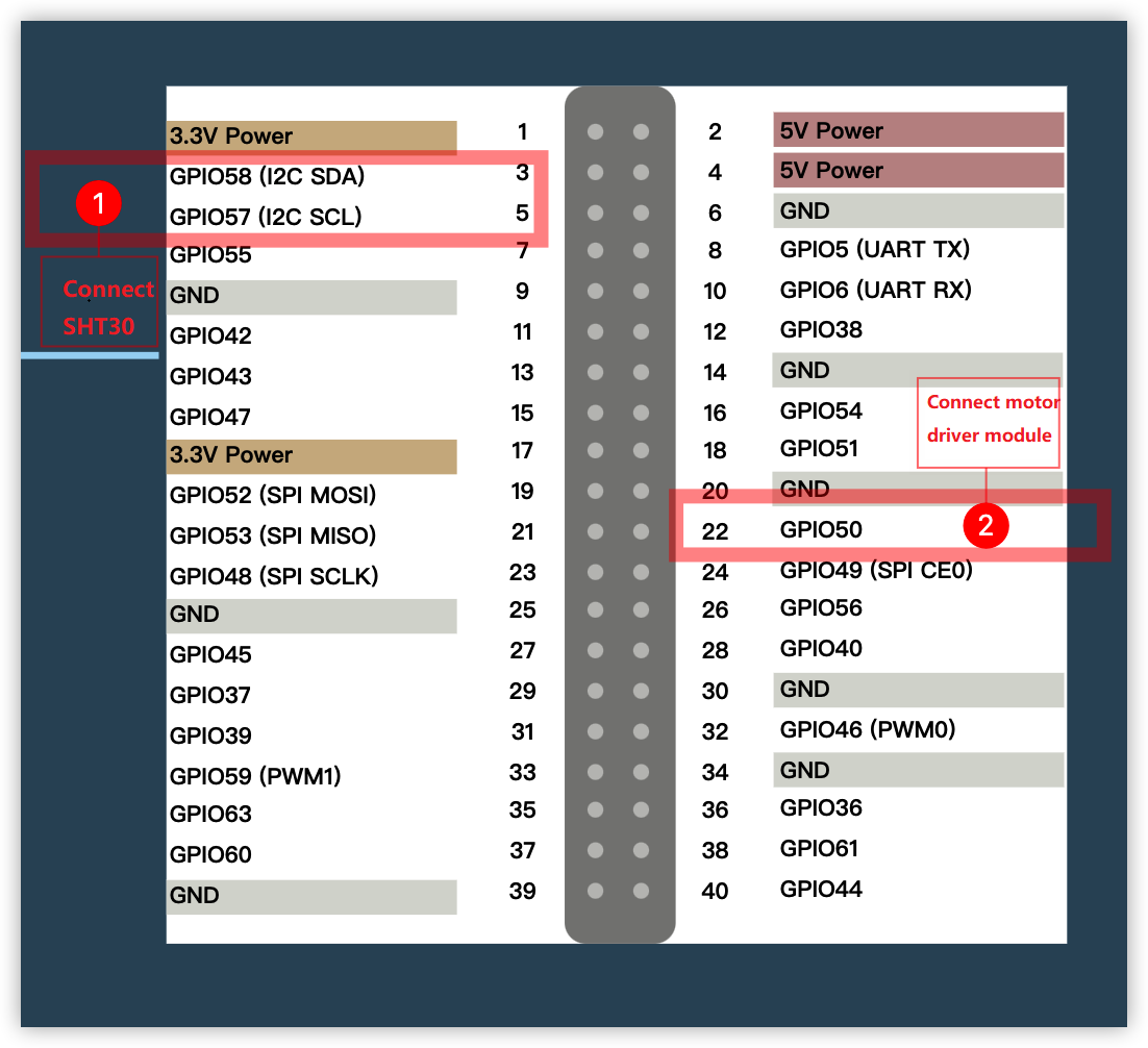
Connection:
Note:
The power supply voltage should be determined based on the actual sensor used. The module in this demo uses a 5V power supply voltage.
4. Coding
In this demo, the use of SHT30 temperature sensor and humidity sensors has been explained in detail in VisionFive 2 SBC Temperature and Humidity Sensor Use. Please read this in advance to understand.
In addition, StarFive also provides an application note (Python) - Using VisionFive 2 to Make An LED Blink at the PWM Frequency, demonstrating how to use PWM to control the LED. The PWM control in this demo is based on this application guide, please review and understand in advance.
Then, we write the following program:
# file: ~/projects/sht3x/sht3x_fan_test.py
import time
from sensirion_i2c_driver import I2cConnection
from sensirion_i2c_sht.sht3x import Sht3xI2cDevice
from sensirion_i2c_driver.linux_i2c_transceiver import LinuxI2cTransceiver
import VisionFive.gpio as GPIO
GPIO.setmode(GPIO.BCM) #set pin numbering system
fan_pin = 22
GPIO.setup(fan_pin, GPIO.OUT)
p = GPIO.PWM(fan_pin, 1000)
p.start(0)
p.ChangeDutyRatio(0)
# Open SHT3X device
i2c_transceivervice = LinuxI2cTransceiver('/dev/i2c-0')
sht3x = Sht3xI2cDevice(I2cConnection(i2c_transceivervice))
while True:
# read the value of temperature and humidity
temperature, humidity = sht3x.single_shot_measurement()
if temperature.degrees_celsius<=25:
fan_speed = 0
elif temperature.degrees_celsius>=35:
fan_speed = 0
else:
fan_speed = int((10 - (35-temperature.degrees_celsius)) * (100/10))
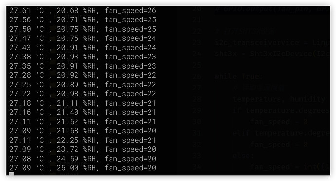
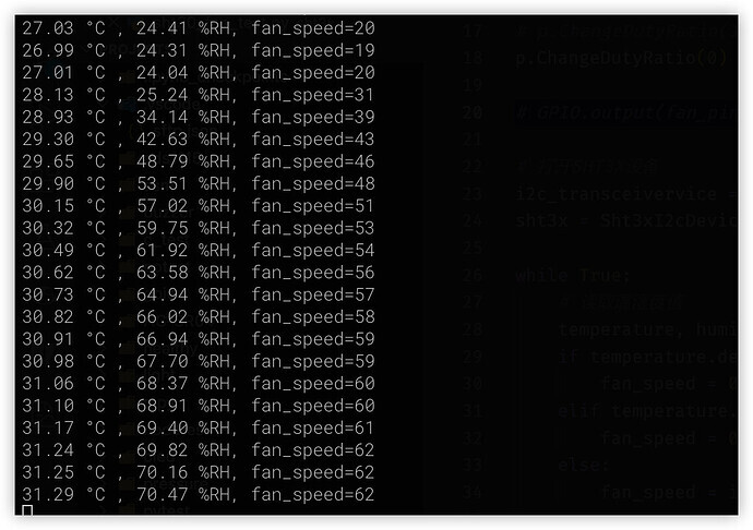
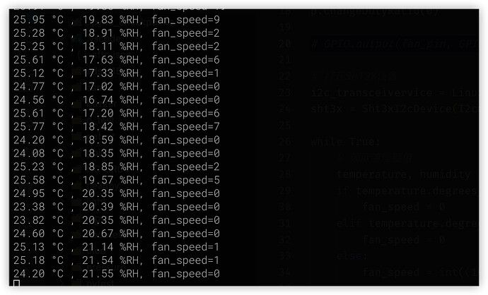
# Print current data and calculate result
print("{:0.2f} °C , {:0.2f} %RH, fan_speed={:d}".format(
temperature.degrees_celsius,
humidity.percent_rh, fan_speed))
# Set the fan speed
p.ChangeDutyRatio(fan_speed)
time.sleep(1.0)
In the above code, we first read the temperature value from SHT30, and then convert it to the corresponding PWM duty cycle based on its value:
-
When the temperature value is less than or equal to 25 ℃, set to 0 and the fan stops
-
When the temperature value is greater than or equal to 35 ℃, set to 100 and the fan runs at full speed
-
When the temperature value is between 25 ℃ and 35 ℃, the duty cycle=(10- (35- current temperature value) * 10
The core code of the PWM output control section is as follows:
p = GPIO.PWM(fan_pin, 1000)
p.start(0)
p.ChangeDutyRatio(0)
Among them:
-
Use GPIO.PWM (fan_pin, 1000) to specify the output GPIO and switching frequency
-
Then start PWM0
-
When usingChangeDutyRatio to set the output duty cycle, the maximum is 100.
5. Operation result
To run the above program, you also need to install the corresponding StarFive GPIO support library, as follows:
# Install extension library
sudo pip show VisionFive.gpio
After writing, run sht3x_fan_test.py and then change the ambient temperature of SHT30 to trigger a change in fan speed.
python3 sht3x_fan_test.py
-
In normal condition, the fan speed is average
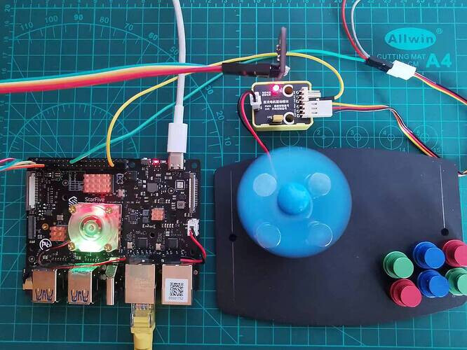
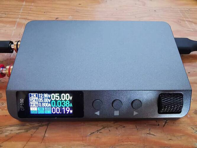
-
When the temperature is high, you can press and hold the black probe part of SHT30 to increase the fan speed
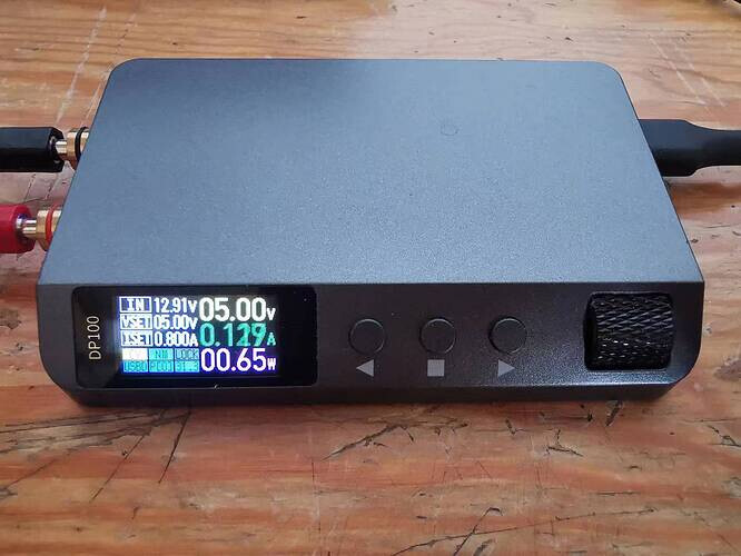
-
When the temperature is low, you can use a frozen iron rod to contact the black probe part of SHT30, lower it to 25 ℃ or below, and the fan stops


6. Summary
In this demo, we learned how to use the temperature sensors to control fan speed.
There are many practical application scenarios for PWM control, except for in fan control, which is widely used in lighting control, servo control, robot control, aircraft control, and other aspects.
For example, there are many so-called eye protection lights that actually control the output of PWM through a light sensor to control the brightness of the light.
