What kind of SSD can be used?

As an update, the M2 6mm screws arrived, and the Patriot P300 is now secured in place by one of these.

So far, no issues with the SSD. It was fine hanging from the slot for weeks, too.

Hmmm. The problem may very well be power-related, but I don’t think it’s as simple as one might hope.

I’ve tried two additional USB-PD supplies/cables. The first is a 45-watt supply with an integral cable (I believe it was originally for a Chromebook). The second is a 100-watt UGreen supply, with a new Anker USB cable spec’ed for 60 watts of power delivery.

The results with these supplies is the same as before: the system will recognize the NVMe about one time in three. Whether I soft-reboot, button-reboot, or power-cycle the board between attempts doesn’t appear to matter.

Now, the interesting thing I’ve noticed is this. On the successful attempt, both PCIe bridges come up (the USB subsystem is behind the first, and the NVMe is behind the second), and there are no complaints in the dmesg log.

On the unsuccessful attempts, only the first PCIe bridge comes up. The second reports “link down”, and neither the bridge nor the NVMe behind it is enumerated. AND (this is the interesting part) the boot log shows “USB overcurrent condition” at right about the same time… and there’s nothing at all connected to any of the USB interfaces!

So, something seems to be going wonky with power… but it beats me what it is. It could be a bad board, or a bad NVMe that’s somehow dragging down power across the board (but with a 60-watt cable/supply combination that seems odd) or something else amiss.

I’d gladly upload the logs and lspci, but the forum won’t let me (yet) as I’m still a new user.

1 Like

The VN679 is specified for 5.5V → 24V input and 5V 8A continuous output.
It is a buck regulator and doesn’t claim compliance with USB power delivery.
I have noticed requirement for a 30W supply for the VisionFive2 board, but does that include peripherals ?
I wouldn’t use an extended (>3Amp) supply (>60W) which can take you to the absolute maximum rating 28V input of the VN679.
I try to avoid absolute maximum ratings !!!
I don’t know how the 5.5V input relates to the USB 5V output ???
I have a USB-C 45W supply which seems to be running perfectly.
USB overcurrent sounds like the supply isn’t switching up voltage to keep the current <3Amp.
I would prefer a 2.1mm DC plug for power supply as found on numerous SBCs which would support 12-24VDC @ 2-3Amp. The usb-c is ???
OR use a USB specified input regulator

The usb-c is ???

I own a usb power monitor. According to its display, my VF2 board seems to negotiate and run off 12v from my usb-pd power supply.

that sounds good,
so the firmware is doing the right thing

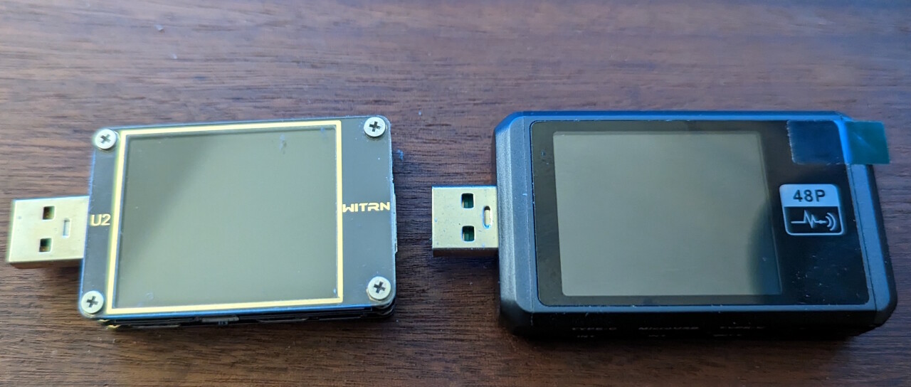
I have had the same experience with 3 different Quick Charge 3.0 power supplies and also with two different USB power monitors, both of which, even when connected to different PD power supplies, only output Quick Charge 3.0. If I connect the VF2 v1.2a directly to a PD power supply without a power monitor, this behaviour does not occur.

Quick Charge 3.0 power supplies first start at 5V, switch to 12V quite quickly, switch back down to 5V when restarted and do not switch back up to 12V afterwards.

Here is a short video that hopefully makes this behaviour clearer: Quick Charge 3.0 power supplies at VF2 SBC v1.2A


I now have a little more time and want to do a cross-check with my VF2 v1.3b and will then report back.

2 Likes

Very interesting - thank you! It’s more than slightly reassuring to know that I’m not the only person seeing this sort of issue.

It’s feeling to me at this point as if the PD power-negotiation process may very well be involved here. Perhaps the board and the supply are negotiating a switch to a different voltage level, in a way (or at a time) which causes a brief brown-out during the switchover, at a time when the NVMe is drawing more current or is more vulnerable to voltage fluctuations (e.g. during PCIe link training)?

I’m not too concerned about a high-power adapter causing an over-voltage condition… assuming that the adapter and the VisionFive are competently designed, the VisionFive’s PD chip should never request a power-profile voltage higher than the board can handle, and the supply should never send a voltage higher than is in the requested profile. (Of course, I may be assuming more than I should :slight_smile: )

The board design documentation says that one option for powering it, is to apply a fixed voltage (between 5 and 20 VDC) on the USB C power pins. The schematic agrees, as the USB C VBUS pins are routed fairly directly (through a fusible resistor and some bypass caps) to the input of U26, the buck regulator which outputs the VCC5.0 supply.

The regulator doesn’t seem to have any control connections at all to U27, the USB C power management chip. It simply bucks down whatever incoming voltage is presented to it, to create a should-be-stable 5-volt supply.

So, completely avoiding the whole USB C PD / QC concern might make for more reliable operation. No negotiation, no supply-voltage changes, no chance for glitches during voltage changes. Wire up all four USB C bus-power contacts in parallel (ditto for the grounds) to minimize voltage drop. Might beworth sacrificing a USB-A-to-C cable to make up a supply like this.

Of course, one would have to be VERY careful in making up a supply like this for this board. You’d want to hang a big red warning sticker on the end of its dedicated cable… “VISIONFIVE 2 ONLY, WILL DESTROY OTHER DEVICES VIA OVERVOLTAGE!!”

Another possibility is that the board itself isn’t capable of delivering enough power to the M.2 slot under all conditions - i.e. it doesn’t comply with the PCIe M.2 specs. Or, perhaps, some NVMe SSDs try to pull more current than the M.2 spec allows. Compatibility is a tough issue, and sometimes when two devices each try to push right up to the spec limits, things go sour and behavior becomes intermittent.

(I ran into a problem like this latter in a previous job. A SOC processor which pushed memory-bus transaction speeds up to the limit from one side, and some DRAM chips which could just barely make the spec in the other direction, would sometimes occasionally fail to meet in the middle… causing the “atomic” read-and-exchange memory access to fail… causing the operating-system mutex() operation to allow two threads to grab the same mutex at a time. You can imaging the havoc which resulted.)

2 Likes

I’m inclined to agree.

I think it is worth putting this here: The USB-PD circuitry from the 1.3b schematic:

U27 is a 12V usb-pd charge controller, U29 is a usb-pd charge controller set to 12v by R91291. Both are connected to the USB-C data and cs lines. Neither is connected any further, they do not ‘charge’ anything, they exist only to do the USB-PD negotiation.

One or the other will be fitted depending on suppliers and availability, not both. This allows StarFive to work around supply-chain issues.

I’m wondering which one you have?

Edit: Also, since this process is not controlled by the firmware, I wonder if a delay to allow the voltage to switch before querying the NVMe might work around this.
Edit2: Since the USB-C data lines are connected the the JH7110 USB2.0 lines, albeit decoupled by some resistors, is it possible that the JH7110 is trying to find a USB2.0 hub or whatever and preventing the PD negotiation…

3 Likes

I have also just found that out. I found the following information on U29 CH224 (U28 is certainly a typeo of yours), which confirms what you described, i.e. permanently 12V. But this contradicts the behaviour I observed. Unfortunately, I did not save the design schematics of version 1.2a locally in time.

I have not found a working source for the CH224D (error 404), only for the CH224K.
CH224K Low-cost USB-PD Sink Controller

3 Likes

@SunWukong I have the 1.2 schematics, I just did a quick compare and this part of the design is unchanged between 1.2 and 1.3.

I don’t think board revision should affect this (unless there are layout changes between the two that somehow matter).

I’m more interested in which PD chip is fitted and if that is a factor. Once home I’ll check my board.

2 Likes

On my board, there’s an unlabeled 20-pin IC located between the USB-C jack and the CSI - I’m guessing that this is U28. There’s an un-stuffed 32-pad layout nearby, and I’m guessing this is for U27. So, I believe I have the CH224.

Hmmm. I thought that the PD negotiation was done entirely over the USB-C CC lines, and didn’t utilize DATA. I could be wrong, though (happens often enough :slight_smile: )

3 Likes

I’m out and about right now, but iirc one is on the top of the board, and the other underneath…
The top and bottom silkscreens are published along with schematic. They are super useful to identify component locations.

1 Like

I have just tested it with my VF2 v1.3 (Debian Image 202302) and unfortunately I did not notice any difference. With QC 3.0, a reboot causes a switch to 5V and my (Transcend TS512GMTE220S 512GB M.2) SSD is then also no longer recognised. On a PD power supply, the SSD is also recognised after a reboot.

3 Likes

Hmmm. The EMMC socket is on the bottom, but I don’t see any other padprints down there which look suitable for either of those parts.

The silkscreen PDFs don’t render clearly enough for me to be sure about the part identifiers, alas. If I zoom them up enough to see the markings in the center of the footprints, the text is blurred to the point of being unreadable.

2 Likes

An afterthought -
at power-up what was the initial voltage coming out of your supply ? 5V, 5.5V or 6.0V ?
and how long before negotiating the switch to 12V ?

My bad, they are both on the top. My pdf viewer won’t zoom in far enough either, at least in chrome. But these are vector diagrams in the PDF and I was able to extract them with inkscape+poppler.

Here is the relevant bit; cut, pasted, scaled and edited in inkscape.
visionfive-1.3b-pd-chip-locations

…and an okay-ish picture of my board…

So I have a CH224D too, I suspect everybody is getting he same at the moment :wink: unless these parts are really low on supply…

2 Likes

Supply is 5V (usb power monitor reads 5.001V).

When attached to VF2, it immediately becomes 12V (~11.87V).

2 Likes

Good to know, thanks. My USB power monitor is in a package which hasn’t left China yet, so it’s hard to get a reading on my system…

Thinking for a bit about what easytarget suggested - possibly, when Linux boots and the USB drivers start up, the board is going through a USB-client reset or enumeration process which touches the USB C port. This might cause the upstream USB host (charger or supply in this case) to reset its USB PD or QC logic, dropping back to 5 volts of output. It might take a while for the supply and the board’s CH224D (or whatever) to go back through the PD negotiation process and switch back up to 12 volts - and perhaps this doesn’t always happen properly, or at all?

Even if it does happen, the step-down to 5 volts might be occurring at just the worst possible time… when the core CPUs are running at full speed trying to bring up the kernel, and when the NVMe is going through its own link negotiation and training (which might be a high-power moment if it tries to use a high clock rate on the interface). I could easily see a momentary brown-out occurring under these circumstances… and that might account for both the NVMe failure-to-train, and the “USB overcurrent” warning (which might really mean “under-voltage detected on the downstream USB power pins”?).

It would be interesting looking at the VBus DC voltage on the board, between the USB C jack and the buck regulator, and see if it bobbles during the boot process. The schematics indicate a test point, somewhere thereabouts… I wonder if it’s actually accessible and safe to tack a test lead to…

3 Likes

Well, I think I just ruled out that hypothesis (or at least the simplest version of it).

I haven’t found the test point for Vbus, but I found that the incoming power is present on one pad of R9127 - the large SMD resistor closest to the USB-C jack. With my 45-watt supply connected, this pad is sitting up right around 9 volts, with a small amount of what looks like switching noise (reduced for a moment when I reset the board). (I’m not sure why this charger isn’t negotiating 12 volts - need to wait for my PD analyzer to arrive.)

I held a scope probe on this pad, with the scope set to trigger on a falling edge at 8 volts. I then ran the board through half-a-dozen reset-and-boot cycles. In several of these cycles, the NVMe was not seen, and the “USB over-current” diagnostic was printed.

The 9-volt supply voltage was rock-solid throughout. The only time the scope triggered was when I removed the probe from the pad. There was no indication that the supply was dropping DC down below 8 volts.

I then switched to my UGreen 100-watt USB PD supply, with Anker 60-watt cable, and repeated the test sequence.

Voltage at the resistor was 12 volts. I set the scope trigger to falling edge, 11 volts. After half a dozen reboot cycles, the NVMe was seen 3-4 times and absent the others (with the USB over-current condition being reported in the latter). The scope didn’t trigger until I removed the probe at the end of the test. No drop down to 5 volts, not even a significant sagging below 11.

So, my friends… whatever’s causing the NVMe detection failure, and the USB over-current condition warnings, can occur even when the incoming voltage is in the 9-12 volt range, and isn’t dropping out by even a volt. At this point I don’t see evidence of USB PD (or QC) being directly involved.

I guess that’s good news, in a sense, as it seems to remove one big variable (USB supply negotiation protocol / quirks) from the equation.

3 Likes

I have now watched the video several times at reduced speed (0.25). I wanted to know when exactly the drop to 5V happens. Quite directly after the message “reboot: Restarting system” and quite a long time before “U-Boot SPL …”.

I have switched both my power monitors to protocol display mode, so I know that they both always convert PD at the input to QC 3.0 at the output. @rvalles can you please also display the current protocol on your power monitor? I assume your device uses the protocol of the input for the output. With my PD power supply units without power monitor, I had no problems with the SSD.

I am now sure we both have different problems that we should not lump together. I think I read that you use different PD power supplies, which I have no problems with. My problems only occur in connection with QC 3.0 and only the successor QC 4.0 is compatible with PD (or is supposed to be compatible).

USB-C is an “egg laying wool and milk sow”, as we say in Germany, and can be hell for developers, manufacturers and consumers.
All About USB-C: Manufacturer Sins

2 Likes