According to StarFive, developers have successfully implemented robot servo control on VisionFive/VisionFive 2, and the specific instructions are as follows:
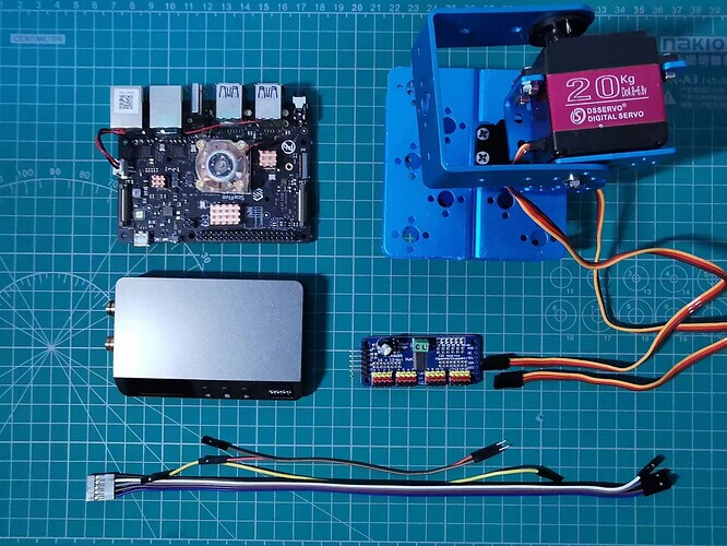
1. Preparation
- Development board: VisionFive/VisionFive 2
- Servo control board: PCA9685 16-lane servo control board
- Robot platform: Base, bracket, and two DS3120 20KG servo
- Digital power: 5V DP
- DuPont Line: Many


2. The principle of servo control
In this demo, PCA9685 is used to control the robot servo.
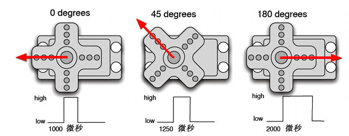
The core of the servo is the DC motor. Through the potentiometer and gear, when different PWM (pulse width modulation) signals are input, different rotation angles can be achieved. Usually, the period of a standard PWM (pulse width modulation) signal is fixed at 20ms (50Hz), and theoretically, the pulse width distribution should be between 1ms and 2ms. However, in reality, the expected pulse width is between 0.5ms and 2.5ms, and the pulse width corresponds to the servo angle of 0 ° to 180 °. Due to different manufacturers of steering gear, the rotation angle of different brands of steering gear may also vary for the same signal. In this course, the DS3120 20KG servo is used, which can be controlled using a 60Hz WPM signal.
A servo usually has three pins, namely power(+5V), Gound(0V), and Control(PWM):
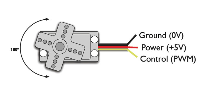
Due to the fact that controlling the servo is essentially controlling the operation of its internal DC motor, and the current required by the DC motor usually exceeds the output current of the GPIO port of the development board, when using the servo, a dedicated external power supply is generally required to power the servo to avoid burning the SBC.
When designing robots, it is often necessary to have a considerable number of servo motors to achieve the actions of different parts. If all of them are connected to the development board, there may be insufficient pins. Therefore, when controlling the servo, the servo control board is generally used.
In this demo, we use the PCA9685 16-lane servo control board, as follows:
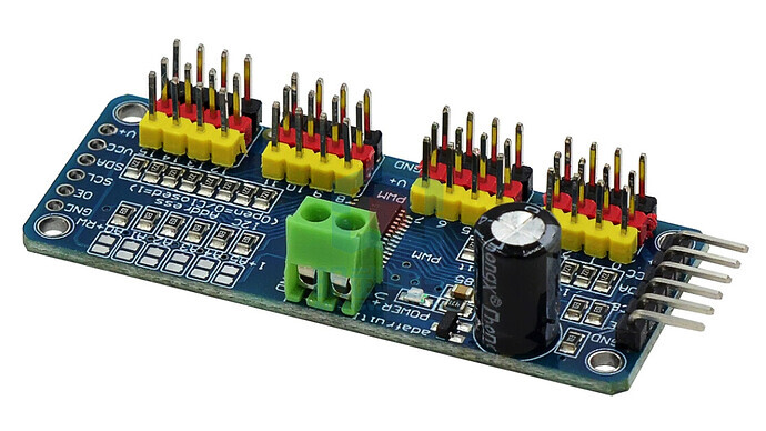
This servo control board is connected to the development board using the I2C interface, and can communicate with 4 GPIOs. The16 servos can be controlled through the board. In practical, more servo control can also be achieved by connecting multiple control boards in series.
3. Connection
Refer to the following figure and connect PCA9685 to VisionFive:
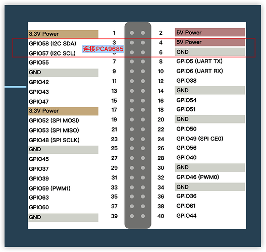
Connection:
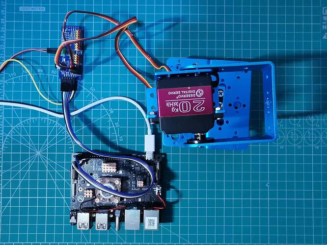
The robot platform used in the demo consists of two servos, which can be connected to the 0 and 1 port of the servo control board.
After the connection is completed, the following instructions need to be used to check and ensure that the servo control board is connected correctly:
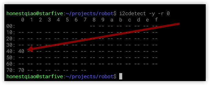
The output result 40 in the above figure represents the default I2C address 0x40 of PCA9685, indicating that the connection is correct.
Note:
- The power supply voltage should be determined based on the actual sensor used. This demo uses a 5V power supply voltage.
- Digital power supply is required to supply power to the servo control board.
- On the servo control board, VCC is used to connect the 5V output pin of VisionFive, and V+ is used to connect the 5V output of the digital power supply.
- If the controlled servo requires a higher voltage, a green power supply terminal can be used for power supply, and the voltage can be 6-12V according to actual needs.
4. Coding
In Python programs, we can communicate with the PCA9685 servo control board through the third-party library PCA9685-driver to achieve control of the servo.
Firstly, we need to write the following program robot_test.py:
# -*- coding: utf-8 -*-
# file: ~/projects/robot/robot_test.py

from pca9685_driver import Device
import time

SERVOMIN = 150
SERVOMAX = 650

# 0x40 from i2cdetect -y -r 0
dev = Device(0x40, bus_number=0)

# set the pwm frequency (Hz)
dev.set_pwm_frequency(60)

dev.set_pwm(0, SERVOMIN)
dev.set_pwm(1, SERVOMIN)

while True:
    for i in range(SERVOMIN,SERVOMAX,1):
        print(i)
        duty = i
        dev.set_pwm(0, duty)
        dev.set_pwm(1, duty)
        time.sleep(0.01)

    for i in range(SERVOMAX,SERVOMIN,-1):
        print(i)
        duty = i
        dev.set_pwm(0, duty)
        dev.set_pwm(1, duty)
        time.sleep(0.01)
In the above code, the PWM upper and lower limits for servo control are first defined, ranging from 150 ℃ to 650 ℃, corresponding to 0 ℃ to 180 ℃.
Then use pca9685_ driver to initialize the servo control board, sets the PWM frequency to 60Hz, and sets both 0-lane and 1-lane as the minimum values.
In the final cycle, first change the angle of the servo from small to large, then from large to small, and continue the cycle.
5. Operation Result
To run the above programs, it is also necessary to install the corresponding third-party support libraries:
# Install extension librarise
sudo pip install PCA9685-driver
After writing, run robot_ test.py program, you can see the action of the servo.
python3 robot_test.py
The actual action can be viewed on bilibili:
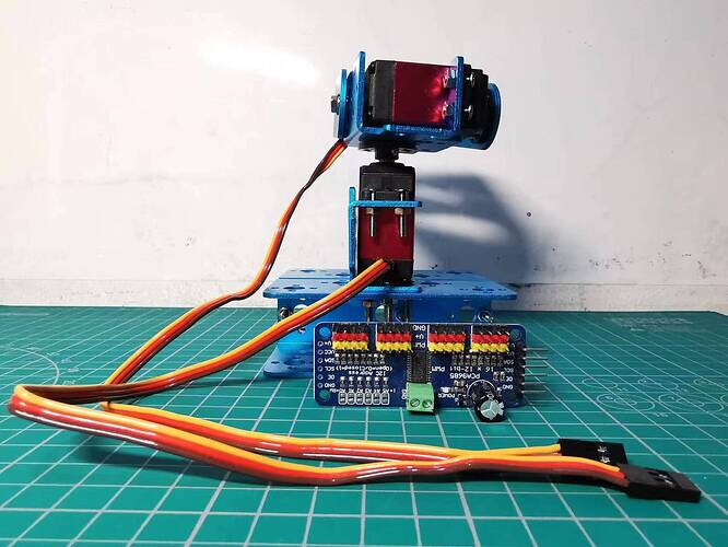
Based on the above program, we can design a more practical program.
The following example shows a small toy attached on the servo. Our program allows the small person to bow and thank the “audience” in front, on the left, and on the right, and finally face forward.
The specific code is as follows:
# -*- coding: utf-8 -*-
# file: ~/projects/robot/robot_test.py

from pca9685_driver import Device
import time

SERVOMIN = 150
SERVOMAX = 650

SERVOMID = int((SERVOMIN+SERVOMAX)/2)

# 0x40 from i2cdetect -y -r 0
dev = Device(0x40, bus_number=0)

# set the pwm frequency (Hz)
dev.set_pwm_frequency(60)

dev.set_pwm(0, SERVOMID)
dev.set_pwm(1, SERVOMID)
time.sleep(1)

if __name__ == '__main__':
    for i in [SERVOMID, SERVOMIN, SERVOMAX]:
        dev.set_pwm(0, i)
        time.sleep(0.5)

        for j in range(SERVOMID,SERVOMAX):
            dev.set_pwm(1, j)
            time.sleep(0.01)

        for j in range(SERVOMAX,SERVOMID,-1):
            dev.set_pwm(1, j)
            time.sleep(0.01)

        time.sleep(2)

    dev.set_pwm(0, SERVOMID)
After writing, run the robot_ test2.py, you can see the actual actions of the small toy on the servo.
python3 robot_test2.py
The actual action can be viewed on bilibili:
5. Summary
In this demo, we learned how to use the servo control board to achieve robot servo control and achieve specific actions.
Because the PCA9685 servo control board can control up to 16 servo motors, and multiple cascades can control more, it is widely used in situations involving robot servo applications.
If we have 4 servo motors and appropriate auxiliary equipment, we can achieve simple robot forward and backward movement. Of course, to achieve stable control, specialized algorithms need to be used for control.